- Автоматизация
- Антропология
- Археология
- Архитектура
- Биология
- Ботаника
- Бухгалтерия
- Военная наука
- Генетика
- География
- Геология
- Демография
- Деревообработка
- Журналистика
- Зоология
- Изобретательство
- Информатика
- Искусство
- История
- Кинематография
- Компьютеризация
- Косметика
- Кулинария
- Культура
- Лексикология
- Лингвистика
- Литература
- Логика
- Маркетинг
- Математика
- Материаловедение
- Медицина
- Менеджмент
- Металлургия
- Метрология
- Механика
- Музыка
- Науковедение
- Образование
- Охрана Труда
- Педагогика
- Полиграфия
- Политология
- Право
- Предпринимательство
- Приборостроение
- Программирование
- Производство
- Промышленность
- Психология
- Радиосвязь
- Религия
- Риторика
- Социология
- Спорт
- Стандартизация
- Статистика
- Строительство
- Технологии
- Торговля
- Транспорт
- Фармакология
- Физика
- Физиология
- Философия
- Финансы
- Химия
- Хозяйство
- Черчение
- Экология
- Экономика
- Электроника
- Электротехника
- Энергетика
Felec = -^-u(h-h*) (13)
(2)
(a)(b) Laser
(b) Laser
|
|
| Photo-detector |
| Photo-detector |
 AFM cantilever
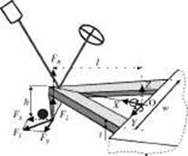
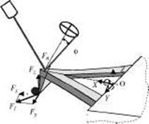
Figure 3. Cantilever deflection measurement using laser beam and a quad-photodetector system. Definition of 3D contact forces when the AFM probe tip is (a) at rest and (b) actuating a nanoparticle, using a pushing strategy Courtesy of Professor Antoine Ferreira, Laboratoire Vision et Robotique of Bourges, France.
6 Virtual Reality and Haptics in Nano- and Bionanotechnology
where тх causes the cantilever end to twist at an angle вх along the x-axis, ry causes the cantilever to bend 8Z in z-direction, and tz causes the cantilever to bend 8y in y-direction. Using the quad-photodiode detector, вх and 8Z can be obtained by Eq. (3), and 8y is not measurable.
@x = KlSl
(3)
Here Kl and Kn are constants that need to be calibrated, and Sn and Sl are the normal and lateral signal outputs of the quad-photodiode detector. Because ту is caused by Fz and Fx, and we cannot remove the effects of Fx from the signal, we define a pseudo-force Fn along the z direction, as shown in Fig. 3, such that
Fn = ~j=Fz + hlFx (4)
This pseudo-force is the normal force measured by Eq. (1). It is clear that Fn «a Fz because (hi I) is usually very small. Suppose the tip lateral motion direction has an angle ф with respect to the x-axis of the cantilever frame; then the lateral force Fl must be opposite to the motion direction, and its amplitude can be found by:
Fl = ^ф (5)
where Fy is measured by
here, kl = Gwt3/3Llt2 is the torsional constant of the cantilever and G is the shear modulus. The lateral force in x-direction can be calculated by
Fx = Fy tan ф (7)
Then the 3D forces represented in the AFM frame are
[FPx, Fpy, Fpzf = BT\FX, Fy, Fzf (8)
where R is the rotational matrix between the workspace and the cantilever frame. By feeding the 3D forces [Fpx, Fpy, Fp2]T to a haptic device, the operator can feel the forces, which are proportional to the actual forces acting on the cantilever.
Thus, piezoresistive measurement of the deflection of an AFM-like cantilever is a very promising approach to implement in nanomanipulation systems. Piezoresistive cantilevers are advantageous for nanohandling devices, where laser detection systems limit their mechanical design and motion capabilities. However, the deflection resolution is almost 10 times worse than laser detection one. High-precision measurements require, for example, soft cantilevers with small spring constants, whereas less precise measurements allow the use of stiffer cantilevers with corresponding better-handling facilities of micro-nano-objects. The deflection can be calculated by resistance change (AR/R) of the implanted piezoresis-tors [15]. For a resistor with area AR, the piezoresistive sensitivity is given as
| /AR \ |
\ n
\ л per Unit Load
^ '
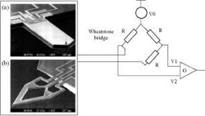
where ttl is the longitudinal piezoresistive coefficient, тгт is the transverse piezoresistance coefficient, load can be a vertical displacement, aL is the longitudinal stress, aT is the transversal stress, and AR is the area of the resistor. The measurement of resistance change itself is performed by an integrated Wheatstone bridge that supplies a voltage change as an output signal. This signal is amplified and provided to the haptic display for further processing and control.
Virtual Reality and Haptics in Nano- and Bionanotechnology 7
The Wheatstone bridge is integrated into the cantilever to achieve a maximally packaged design (Fig. 4a). Most AFM cantilevers have a rectangular shape with a uniform cross section, having a higher sensitivity in the normal force and small sensitivity for lateral forces. They are not really designed to sense forces along the three dimensions [Fpx, Fpy, Fpz]T. In addition, sensors that are sensible to nanoforces acting in three dimensions are currently being investigated (Fig. 4b) [16]. This sensor with integrated piezoresistors offers a distinctly better resolution for forces in micro- and nano-Newton ranges than does a sensor with attached semiconductor strain gauges. However, as we can see, the laser-based approach requires precise alignment of the laser optics with respect to the cantilever, and the piezore-sistive approach requires a cantilever specially embedded with piezoresistive material and external circuitry to process the output of the sensor.
With OT-based manipulation, typical manipulation can be done through a 2D pointing device such as a mouse or joystick. Usually the manipulation is done in noncontact mode, so there is no direct force that can be felt and rendered on a haptic display. Because of the limited ability of traditional optical microscopy to resolve nanometer-scale structures, OT, unlike AFM and STM, must use other means and must synthesize virtual sensory inputs, such as virtual potential fields, as an abstraction of the potential energy field that is induced by the laser beam, for rendering the haptic display to the operator.
| Figure 4. Structure of a AFM-based piezoresistive force sensing with integration of Wheatstone bridge; (a) force sensing in one dimension and (b) in three dimensions. Reprinted with permission from [16], S. Fahlbusch et al., " AFM-Based Micro Force Sensor and Haptic Interface for a Nanohandling Robot, " IEEE/RSJ International Conference on Intelligent Robots and Systems, Lausanne, Switzerland, 2002, pp. 1772-1777. © 2002, IEEE. |
2. 2. 2. 2. Force-Feedback Display The goal of the force control development is to offer the operator a straightforward and flexible handling of nano-objects with the help of force information. The information representation could be realized by visual interfaces, by haptic devices, or by acoustic interfaces. Using multimodal interfaces for a microrobot-based nanohandling cell, it is possible to provide visual, haptic, and sound force feedback from the nanohandling place. Depending on the sensor information and the requirements for the nanoworld representation, haptic interfaces allow the operator to feel and control the nanoforces during nanomanipulation (usually through an AFM cantilever beam) by hand in case of the lack or absence of visual information. By using a haptic device, it is possible to perform real-time manual control of the force Fc with which the nano-object is handled by the AFM probe tip. It is also possible to control forces that occur during contact of the probe tip or a nano-object with their environment. Figure 5 presents two multidegree-of-freedom haptic devices [87, 17] that allow the operator to feel and control the forces in the nanoworld by hand and to change the position of the microrobot and its AFM-based manipulator by changing the position of his hand in space. This can be the case when nanohandling has to be performed in closed tubes, deep inside complex 3D nanostructures, and so on, or when
Virtual Reality and Haptics in Nano- and Bionanotechnology
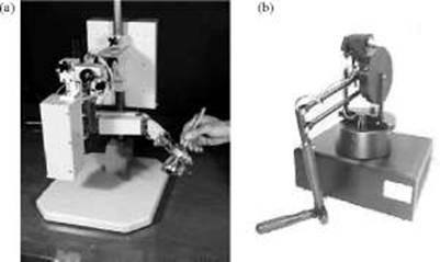
Figure 5. Force-feedback systems for haptic display (a) haptic interface (PHANToM, SensAble Technologies) with six-depth-of-field positional input and three-depth-of-field force output for force-feedback interaction, and (b) six-depth of field positional input and three-depth of field translational inputs. Reprinted with permission from [16], S. Fahlbusch et al., " AFM-Based Micro Force Sensor and Haptic Interface for a Nanohandling Robot, " IEEE/RSJ International Conference on Intelligent Robots and Systems, Lausanne, Switzerland, 2002, pp. 1772-1777. © 2002, IEEE.
it has to be performed in a subnanometer range; that is, below the limits of the resolution of SEM.
Real-time force-feedback control can be also performed through 3D vision-based force sensing on a computer display. Figure 6 illustrates such a nano-Newton scale sensing applied to a microscale cantilever beam, using a computer vision approach. The information representation is visualized directly by the operator through 3D-based simulation graphics. Vision-based nanoforce sensing provides a simple method to use an elastic part as a reliable force sensor. One advantage of measuring nanoforces through the use of computer vision is that it uses equipment that often already exists in a nanomanipulation or biological manipulation station, where a CCD camera mounted with a microscope or a scanning electron microscope exist. Another advantage of this method is that the same technology can be applied to geometries that are more complex than a simple cantilever beam (i. e., nanotube structures).
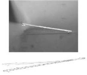
Figure 6. Vision-based force sensing using mechanical deflection of a cantilever by using a deflected beam template matched with deflected beam and 3D graphic reconstruction for user force interaction. Reprinted with permission from [17], M. A. Greminger and B. Nelson, " Vision-Based Force Sensing at Nanonewton Scales, " SPIE International Society of Optics, Microrobotics, and Microassembly III, 2001, Vol. 4568. © 2001, SPIE.
Virtual Reality and Haptics in Nano- and Bionanotechnology 9
Finally, it should be noticed that acoustic interfaces based on 3D sound can help the operator through auditory channels to feel the magnitude of the applied nanoforces [18, 19]. The use of sound information would enhance the user's perception of the nature of the nanoworld [20]. For example, sound plays a large role in determining how we perceive events, and it can be critical to giving the user/viewer a sense of immersion. Vibration feedback could be used for tactile display to sense impact events such as tapping and handling in the nanoworld. For vibration feedback in virtual environments, a model is used to determine the forces to display [21]. When the above-mentioned techniques are unified, the teleoperator is approaching the state of full immersion, or telepresence.
2. 2. 3. Inaccurate Models at Nanoscale
The operational remote environment is actually a hostile environment to humans because nanoworld component behavior is very complex to understand and to manipulate. Moreover, as a human operates based on macroworld model physics, tasks can not be easily executed by the operator. When the objects are scaled down to the nanometer scale, there are many significant changes in the physics and properties of materials: surface-to-volume ratio increases (i. e., surface forces, friction, and drag forces dominate inertial forces; surface properties; could dominate bulk properties; and friction becomes also a function of contact area); dynamics of the objects become faster; and heat dissipation increases. For parts with dimensions of less than 100 /лт, adhesive forces such as electrostatic, van der Waals, and surface tension become dominant with respect to inertial forces and make it difficult to grasp and release nanoparts during operation. Understanding of nanodynamics and the effect of various nonlinear forces, together with a reliable modeling approach, is a critical issue for the success on manipulations tasks. Assuming that the AFM tip is spherical, nanoforces between a sphere, a particle, and an elastic flat substrate are to be modeled for simulating the nanomanipulation interactions in a VR environment.
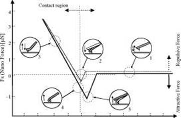
2. 2. 3. 1. Scaling Effects Figure 7 illustrates quantitative information on forces between the AFM probe tip and a sample as a function of tip-sample distance in ambient conditions. If the AFM tip approaches the sample surface, the cantilever is deflected from its original position. During the approaching phase of the tip to the surface there is no tip-sample contact. Tip-sample contact occurs at the point second point, where the tip jumps into contact with the sample as a result of van der Waals and electrostatic force. The cantilever is deflected further under an increasing force at the linear part of the force-distance curve.
| Non-Contact region |
 -0. 4 -0. 3 -0. 2 -0. 1 0 0. 1 0. 2 0. 3 0. 4 0. 5 0. 6 (Tip-Sample Distance) [um]
Figure 7. Example of force-distance curve during approach to and retraction from a flat silicon surface with piezore-sistive AFM nanoprobe Courtesy of Professor Antoine Ferreira, Laboratoire Vision et Robotique of Bourges, France.
Virtual Reality and Haptics in Nano- and Bionanotechnology
When the movement retracts in z-direction, the force of the cantilever is decreasing. Adhesive forces between the tip and the sample keep the tip in contact with the sample beyond the previous first-contact force. This leads to negative deflection of the cantilever. The cantilever then breaks free from to the surface (" pull-out" ) and returns to its starting deflection. The main forces causing the noncontact attraction and contact repulsion are modeled and explained here.
Van der Waals forces exist for every material in every environmental condition (like the gravitational force in the macroworld), and they depend on the object geometry, material type, and separation distance. They are caused by a momentary dipole moment between atoms, resulting from interaction between electrons in the outermost bands rotating around the nucleus. If we assumed that the end-tip of an AFM cantilever is ideally spherical shaped, the interactive force between a spherical probe tip and a spherical particle can be estimated from the interaction force resulting from van der Waals forces between two spheres [22]:
p __
vdw
HCRtR2 \m\R\ - [C2 - (Rt - R2)2][C2 - (Rt + R2)2]
(10)
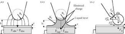
where R1 is the curvature of the spherical probe tip and R2 is the radius of the sphere-shaped sample, C is the distance between two centers, and H is the Hamacker constant. The equivalent Hamaker constant for two different materials is H12 = y/H^^ in which H1 and H2 are Hamacker constants for individual materials. By letting R2 go to infinity, the van der Waals force between a spherical probe and a flat surface (Fig. 8a) is approximated as follows
vdw
2НЩ
3d2(d + 2R1)2
(11)
where d is the distance from a flat surface to a spherical probe tip.
In Capillary forces, the water layer on the surfaces of the probe, particle, and substrate results in an adhesion force. A liquid bridge occurs between the tip and the surface at close contact, as shown in Fig. 8b. Using the macroscopic theory, the adhesion phenomenon is expressed by [23]
2r1
cos# ■ u(-h + L)
(12)
The parameters of this capillary force are в (the contact angle of the meniscus), u(-) (the step function), h (the probe tip/substrate distance), yL (the liquid surface energy for water yL = 72 mJ/m2), e (the thickness of the liquid layer), p (radii of curvature of the meniscus as r1), and R1 (the radius of the probe tip). The parameter is defined as L = 2e (during approaching), which is the thickness of the water layer, and L = 8 (during retracting), which represent the breaking length of the minescus. This force is attractive for values of в less than 90 degrees.
| sample |
 probe tip
substrate
probe tip
substrate
probe tip
substrate
Figure 8. Parabolic nanoprobe tip and a flat surface interacting (a) via the van der Waals, electrostatic force parameters, (b) via capillary force parameters during approach to or retraction from phases, on (c) via interacting forces during positioning of nanoparticles by the AFM tip contact pushing. Courtesy of Professor Antoine Ferreira, Laboratoire Vision et Robotique of Bourges, France.
Virtual Reality and Hap tics in Nano- and Bionano technology 11
Via Electrostatic forces, significant amounts of charge may be generated by friction (during pushing manipulation) and by differences in contact potentials. Grounding the conducting substrate such as Si or Au, the electrostatic forces can be reduced. However, in the case of nonconducting particles, there are charges trapped around the perimeter of particles, and during pushing or contact, triboelectrification induces local charges. These forces occur during adhesion-based manipulation strategy, when the electrostatic force between the sample and the substrate becomes important. During pushing-based manipulation, the charge of the sample is transferred to the tip, which can cause an electrostatic force between the sample and the probe tip (then the sample can stick to the tip during retraction, which is observed in some cases).
Felec = -^-u(h-h*) (13)
where e0 is the permittivity and S is the shared area; U is the resulting voltage difference between the probe tip and the sample. As previously, h is the probe tip/substrate distance, and h* represents the minimal distance by which Eq. (13) is valid.
Frictional forces involves, during pushing (Fig. 8c), the friction between the sample and the substrate (indexed ss) playing an important role. The definition of the friction at the micro-nanoscale can be given as
css = /" ss^ss (14)
where Nss = Fss + Fsf' with Fss = 4irR1yL at contact, and Fext is the external preload, and /iss is the particle-substrate friction coefficient. Also, there is a friction between the tip and the sample (indexed ts) such that F£ c = /i^N^ with Nts = Fts + Ftsext with Fts = 4irR2yL.
Repulsive contact forces come into play as well. The contact area between the sample and the AFM probe tip is very small, so only the deformation between the particle and the substrate along the z-axis is considered. The contact forces are modeled by considering the repulsive elastic deformation/indentation forces with surface adhesion. If we assume small load and high surface forces, the JKR [24] model is commonly used to approximate the contact area prediction.
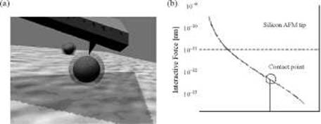
2. 2. 3. 2. Virtual Simulation for Nanomanipulation Tasks These reality-based models could be used to enhance the haptic display of virtual environments at the nanoscale. VR-domain modeling would consist of using this knowledge to construct a 3D model of the environment, which simulates in a realistic manner the nanointeractions (i. e., attractive, repulsive, adhesion, and frictional nanoforces [25, 26]). When a proper virtual environment is available, it will greatly help to design nano-operation activities. For example, it visualizes the virtual movement in the nanoworld during manipulation as a way for planning automatic assembly tasks, it gives virtual force reflection that aids in the development of force control methods for nano-telemanipulation, and it facilitates testing of different manipulator and tool structures before constructing them, reducing the development cost. For example, Fig. 9a shows the physically based simulation of an AFM probe tip contacting a nanosphere. The nanosphere is surrounded by a force field, which corresponds to the minimum distance so that the objects can be attracted to each other. From a physical point of view, this force field represents the combination of noncontact forces at the microworld, that is, electrostatic, adhesive, and van der Waals forces. By implementing the physical model of these noncontact attractive forces, the theoretical distance can be estimated with high precision during nano-positioning (Fig. 9b). However, this does not take into account the physical and geometrical imperfections of the objects and manipulator tip. An experimental calibration procedure allows us to avoid such problems.
Furthermore, haptic-rendering algorithms offer us the possibility of generating an adequate force field to simulate the contour of the object and the surface properties such as friction [27] and texture [28], which enhance the virtual haptic display of nano-objects. Image-based texture maps can be used to modulate any of the surfaces parameters—friction, viscosity, or stiffness—to create different haptic effects. Accurate physical simulations, which
Virtual Reality and Haptics in Nano- and Bionanotechnology
 2 4 6 8 10 12
Distance between AFM tip and Microobject [nm]
Figure 9. (a) Interactive adhesive nanoforces when the AFM-based robot closely approaches the nanosized object, and (b) calibrated interactive force for planned trajectory. Courtesy of Professor Antoine Ferreira, Laboratoire Vision et Robotique of Bourges, France.
have been studied in computational mechanics, can provide a powerful tool for automatically generating elastic deformations. They have been traditionally very expensive in terms of computation time, but they are becoming increasingly affordable with the continually growing performance of computer hardware. The basic approach for contact problems is to detect penetration between objects and compute an appropriate response that eliminates, minimizes, or reduces penetration, especially for biological micromanipulation cells. Figure 10 gives an example of force calculation and 3D display during surface deformation of a biological cell. When the cantilever touches the surface and is pushed further into the surface of the nano-object, a force occurs between the surface and the tip [29, 30]. Thus, the operator can visualize the effect of the interactive force as well as feel the reflected force. To speed up the graphical display, not just the entire shape varying during the object deformation is not implemented but the curved surfaces of the deforming object are approximated, using linearly varying planes.
As it is well known, nano-interaction is not reproducible enough to automate a nano-procedure. Therefore, the use of physically based simulation techniques of 3D multi-body nano-systems would enhance the operator's skills by learning and feeling a realistic nanoworld in an off-line user interaction mode. Then, by practicing the adequate gesture through trial-and-error schemes, the operator would be able to reproduce the nanomanipu-lation tasks in a real environment.
2. 2. 4. Complex Strategy of Nanomanipulation
| Figure 10. 3D Nano-Graphics: force display and surface deformation. To provide the operator with force feedback, the magnitude of the force is displayed as a conic in the computer model. Courtesy of 3D Nano-Graphics. © Dr. Hideki Hashimoto, University of Tokyo, Japan. |
Nanotechnology will involves the planning and the scheduling of assembly sequences in an eutatic environment. At the nanoscale, tasks are defined as conventional ones such as positioning, assembling, grip, release, adjust, fix-in-place, push, pull, and so forth of individual n-objects.
Virtual Reality and Haptics in Nano- and Bionanotechnology
2. 2. 4. 1. Scheduling of Nanohandling It is believed that free-space motion planning
and the geometric assembly constraints in macroworld planners will directly apply in the
microdomain. However, fine-motion planning and precise motion will differ from the
macroworld. As it has been shown previously, the assembly in the nanodomain is not
reversible—motions required to pick up a part are not reverse motions required to release
a part. Figure 11 shows the static forces on the sphere at the various stages of pick up and
release a nano-object during force-controlled adhesion for three-dimensional (3D) assembly
of nanoparticles. The forces involved in the adhesion process are the force of gravity Fg, the
force of surface attraction Fsa = Fcap + Fvdw (if we assume that no electrical charge on the
sphere), and the force of tool attraction Fta. To pick up the part, the force of tool attraction
Fta must be greater than the gravitational force and the force of surface attraction. To hold
the part, the force of tool attraction must be greater than the gravitational force. Finally, to
release the part, the force of tool attraction must be less than the gravitational force and
the surface attraction [31].
To link the macroworld to the nanoworld, a virtual environment of physical simulation in which assembly and motion-planning strategies can be tested is of real interest. Thus, the reliability and efficiency of manipulation tasks can be tested with respect to various tool shapes, different properties of materials in contact (tools, objects, and substrate), adequate texture-reducing adhesion forces, efficient strategies of releasing, and so on. As an example, Fig. 12 shows a virtual simulator developed at Laboratoire de Robotique de Paris 6 [32], testing the releasing strategy by use of dynamics effects. Once the pick-up, holding, and release goal regions are determined, normal assembly and path planning routines can be used to determine assembly sequences and collision-free paths.
2. 2. 4. 2. Three-Dimensional Path and Trajectory Planning Strategies Originally, the
AFM mechanism is based on interatomic force interaction for holding the topology images
of a substrate. It can be applied to imaging all types of particles/samples that are fully or
semifixed on a substrate with homogeneous surface stiffness and interatomic force proper
ties. Changing its function from only imaging to both imaging and manipulation, 3D path and
trajectory planning strategies of an AFM-based force-controlled system are possible for two-
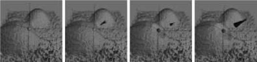
dimensional (2D) positioning of nanoparticles using pushing operation (Fig. 13) [33, 34], for
nanocutting and nanolithography [35] or nanomeasurement of samples such as adenoviruses,
ADN fibers, and so forth [7].
Acceleration
|
|
|
© helpiks.su При использовании или копировании материалов прямая ссылка на сайт обязательна.
|