- Автоматизация
- Антропология
- Археология
- Архитектура
- Биология
- Ботаника
- Бухгалтерия
- Военная наука
- Генетика
- География
- Геология
- Демография
- Деревообработка
- Журналистика
- Зоология
- Изобретательство
- Информатика
- Искусство
- История
- Кинематография
- Компьютеризация
- Косметика
- Кулинария
- Культура
- Лексикология
- Лингвистика
- Литература
- Логика
- Маркетинг
- Математика
- Материаловедение
- Медицина
- Менеджмент
- Металлургия
- Метрология
- Механика
- Музыка
- Науковедение
- Образование
- Охрана Труда
- Педагогика
- Полиграфия
- Политология
- Право
- Предпринимательство
- Приборостроение
- Программирование
- Производство
- Промышленность
- Психология
- Радиосвязь
- Религия
- Риторика
- Социология
- Спорт
- Стандартизация
- Статистика
- Строительство
- Технологии
- Торговля
- Транспорт
- Фармакология
- Физика
- Физиология
- Философия
- Финансы
- Химия
- Хозяйство
- Черчение
- Экология
- Экономика
- Электроника
- Электротехника
- Энергетика
SignalTap II waveform. Interface definition (J4 in the schematic diagram, the pin on the PCB is 1 pin). DA experiment steps. First, connect the ADDA module to the 34-pin standard expansion port of the FPGA Black Gold Development Board (in the event of a p
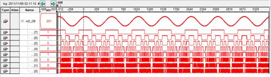
七、 SignalTap II waveform
The waveform below is the data waveform acquired using the SignalTap II tool in the Quartus II software.
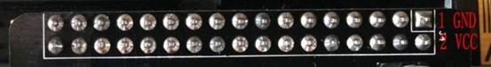
八、 Interface definition (J4 in the schematic diagram, the pin on the PCB is 1 pin)

九、 DA experiment steps
1. First, connect the ADDA module to the 34-pin standard expansion port of the FPGA Black Gold Development Board (in the event of a power loss).
2. When doing DA experiments, you need to have an oscilloscope to match the AD output port (near potentiometer
BNC interface J2) is connected to the oscilloscope interface via the cable we provide.
3. Download the program to the FPGA using the Quartus II software (the test program is available for download in our forum).
4. Adjust the oscilloscope to display the full waveform correctly.
5. You can manually adjust the amplitude of the waveform with the potentiometer (U6).
十、 AD experiment steps
1. First, connect the ADDA module to the 34-pin standard expansion port of the FPGA Black Gold Development Board (in the event of a power loss).
2. This experiment requires the cooperation of the DA experiment, that is, we need to pass the DA output signal to the AD input port. Of course, if you have a signal source, it is better. Use the connection cable provided by us to connect the output interface of the signal source to the AD input interface (J3) (Note: AD port input range: -5V~+5V).
3. Download the program to the FPGA using the Quartus II software (the test program is available for download in our forum).4. Real-time data acquisition with SignalTap II.
十一、 note
1. This ADDA module can be directly used with the updated FPGA Black Gold Development Board and FPGA Black Gold Development Board Student Edition. Previous versions of the Black Gold Development Board (which did not lead to the standard 34-pin expansion port) could not be connected to this module and would need to be tested by jumpers.
|
|
|
© helpiks.su При использовании или копировании материалов прямая ссылка на сайт обязательна.
|