- Автоматизация
- Антропология
- Археология
- Архитектура
- Биология
- Ботаника
- Бухгалтерия
- Военная наука
- Генетика
- География
- Геология
- Демография
- Деревообработка
- Журналистика
- Зоология
- Изобретательство
- Информатика
- Искусство
- История
- Кинематография
- Компьютеризация
- Косметика
- Кулинария
- Культура
- Лексикология
- Лингвистика
- Литература
- Логика
- Маркетинг
- Математика
- Материаловедение
- Медицина
- Менеджмент
- Металлургия
- Метрология
- Механика
- Музыка
- Науковедение
- Образование
- Охрана Труда
- Педагогика
- Полиграфия
- Политология
- Право
- Предпринимательство
- Приборостроение
- Программирование
- Производство
- Промышленность
- Психология
- Радиосвязь
- Религия
- Риторика
- Социология
- Спорт
- Стандартизация
- Статистика
- Строительство
- Технологии
- Торговля
- Транспорт
- Фармакология
- Физика
- Физиология
- Философия
- Финансы
- Химия
- Хозяйство
- Черчение
- Экология
- Экономика
- Электроника
- Электротехника
- Энергетика
Note: Since the accuracy of the circuit is not very accurate, the final output has a certain error. It is possible that the waveform amplitude cannot reach 10Vpp, and there may be problems such as waveform clipping. These are normal conditions.. Waveform
Note: Since the accuracy of the circuit is not very accurate, the final output has a certain error. It is possible that the waveform amplitude cannot reach 10Vpp, and there may be problems such as waveform clipping. These are normal conditions.
五、 Waveform display

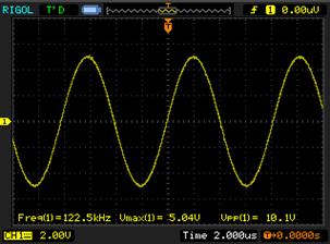
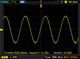
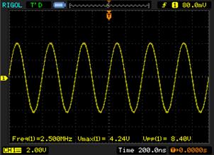
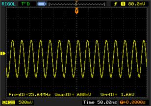
Note: Due to the influence of the amplitude-frequency characteristics, the amplitude of the waveform will decrease as the frequency increases.

六、 Analog-to-digital conversion (AD) circuit
As shown in the hardware structure diagram, the AD circuit consists of a high-speed AD chip, an attenuation circuit, and a signal input interface.
The high-speed AD chip we use is an 8-bit version from AD, with a maximum sampling rate of 32MSPS.
AD9280 chip. The internal structure diagram is shown below
According to the configuration shown below, we set the AD voltage input range to: 0V~2V. 
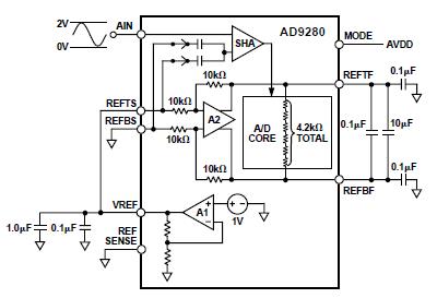
Before the signal enters the AD chip, we built an attenuation circuit with an
The input range of the interface is -5V~+5V (10Vpp). After attenuation, the input range satisfies the input range of the AD chip
(0~2V). The conversion formula is as follows:
When the input signal Vin = 5 (V), the signal input to AD Vad = 2 (V);
When the input signal Vin=-5(V), the signal input to AD Vad=0(V);
|
|
|
© helpiks.su При использовании или копировании материалов прямая ссылка на сайт обязательна.
|