- Автоматизация
- Антропология
- Археология
- Архитектура
- Биология
- Ботаника
- Бухгалтерия
- Военная наука
- Генетика
- География
- Геология
- Демография
- Деревообработка
- Журналистика
- Зоология
- Изобретательство
- Информатика
- Искусство
- История
- Кинематография
- Компьютеризация
- Косметика
- Кулинария
- Культура
- Лексикология
- Лингвистика
- Литература
- Логика
- Маркетинг
- Математика
- Материаловедение
- Медицина
- Менеджмент
- Металлургия
- Метрология
- Механика
- Музыка
- Науковедение
- Образование
- Охрана Труда
- Педагогика
- Полиграфия
- Политология
- Право
- Предпринимательство
- Приборостроение
- Программирование
- Производство
- Промышленность
- Психология
- Радиосвязь
- Религия
- Риторика
- Социология
- Спорт
- Стандартизация
- Статистика
- Строительство
- Технологии
- Торговля
- Транспорт
- Фармакология
- Физика
- Физиология
- Философия
- Финансы
- Химия
- Хозяйство
- Черчение
- Экология
- Экономика
- Электроника
- Электротехника
- Энергетика
Harvesting the Wind: The Physics of Wind Turbines
Harvesting the Wind: The Physics of Wind Turbines
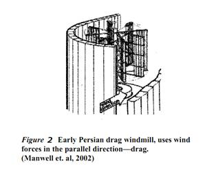
A wind turbine is essentially a very large, inverse fan: the wind produces electricity instead of electricity producing wind. However, because wind turbines run ‘backwards’ and are several thousand times larger than most fans (~85-400 tons), they are much more complicated, especially since it is necessary to get the greatest efficiency and quality at the least cost. Modern wind turbines range from about 40–80m in height, 50 – 85m in span, and 850 kW to 4. 5MW in power. They usually have three blades and almost always have a horizontal axis shaft (like old European windmills) as shown on the left in Figure 1, but there are those with a vertical axis, as shown on the right in Figure 1.

Figure 1
For a horizontal axis wind turbine (HAWT), the plane of the rotor (i. e. the blades and the hub) turns so that the wind is perpendicular to it and can flow around the blades to make them rotate around the hub. The horizontal shaft of the rotor also turns and runs a generator to which it is connected through a gearing system. The generator creates electricity from the mechanical energy and sends the resulting current down the tower to the electrical grid, which supplies electricity to the consumers. Each of these components will be explained in more detail.
Blades
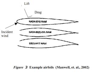
A careful choice of the shape of the blades is crucial for maximum efficiency. Initially, wind turbines used blade shapes, known as airfoils, based on the wings of airplanes. Today’s wind turbines still use airfoils, but they are now specially designed for use on rotors. Airfoils use the concept of lift, as opposed to drag, to harness the wind’s motion. Blades that operate with lift, forces perpendicular to the direction of flow, are almost always more efficient than a drag machine (seen in Figure 2). Certain curved and rounded shapes have proven most efficient in employing lift. Below, in Figure 3, are some examples of the cross sections of blades used for wind turbines.
| 
|
Gearbox
As the rotor does its job by turning at the designated wind speed, the rotor shaft connected to it turns inside the nacelle. The nacelle is a large box at the top of the tower that holds all the mechanics and electronics that are needed to generate electricity. The main components are the gearbox, the generator, the cooling system, the yawing system, and the brakes, as can be seen in Figure 4.
 Figure 4
The first step is to convert the rotor shaft speed into a speed that can be used by the generator. Most generators operate at significantly higher speeds than those at which a wind turbine rotor can reasonably operate. A rotor would have a tip speed greater than the speed of sound if it were to accommodate a standard generator. Gears are particularly useful for changing shaft speed. The gear connected to the rotor shaft has more teeth than the gear connected to the generator. In transferring from a larger gear to a smaller gear, the rotational speed increases and the torque drops, while total power remains the same.
Consider that in one full rotation of the larger gear, the smaller gear rotates many more times, and thus the shaft must move much faster. The gear ratio of Carleton College’s 1. 65 MW wind turbine is 1: 84. 3, so that when the rotor is operating at its rated speed of 14. 4 rpm, the generator shaft is turning at about 1214 rpm.
|
|
|
© helpiks.su При использовании или копировании материалов прямая ссылка на сайт обязательна.
|